Geometry Tolerant Meshing
Note: This feature is under
development. The command to enable or disable features under development
is:
Set Developer Commands
{On|OFF}
Applies to:Volumes, Surfaces
Mesh Type: Triangle, Tetrahedral,
Quadrilateral
Summary:The geometry tolerant
meshing algorithm takes a volume and generates a mesh by ignoring small
features, gaps, slivers, and surface alignment problems in the geometry.
To create a tolerant mesh:
- In the Command Line, type Set Developer Commands On (Set
Dev On).
- On the Command Panel, click on Mesh and then Volume.
- Click on the Tolerant Mesh action button.
- Select Tolerant Mesh from the drop-down menu.
- Enter the appropriate values for Volume ID(s). This can
also be done using the Pick Widget function.
- Select Triangle, Tetrahedal or Quadrilateral
from the Algorithm mennu.
- Select FEM, New or Old.
- Enter the appropriate value for Tolerance Fraction.
- Click Apply.
Mesh Tolerant Volume
<range> {Triangle|Tet|Quadrilateral} {Free} {Fraction <number>}
{Fem|New|Old}
To fix or free an entity:
- In the Command Line, type Set Developer Commands On (Set
Dev On).
- On the Command Panel, click on Mesh and then Volume.
- Click on the Tolerant Mesh action button.
- Select Fix/Free Entities from the drop-down menu.
- Select Fix or Free.
- Select Volume, Surface, Curve or Vertext
from the drop-down menu and enter the appropriate value.
- Click Apply.
Mesh Tolerant [Fix|Free]
[Volume|Surface|Curve|Vertex] <range>
To create a tolerant mesh:
- In the Command Line, type Set Developer Commands On (Set
Dev On).
- On the Command Panel, click on Mesh and then Volume.
- Click on the Tolerant Mesh action button.
- Select Visualize Mesh from the drop-down menu.
- Enter the appropriate value for Volume ID(s). This can also
be done using the Pick Widget function.
- Click Apply.
Mesh Tolerant Volume
<range> Facet
Discussion:
Many geometric assemblies contain imperfections or small features that
hinder mesh generation. These imperfections can be caused by excessive
detail, data format translation errors, poorly constructed initial models
and a variety of other factors. Rather than performing time-consuming
geometry operations to remove these features, the geometry tolerant meshing
scheme will be "tolerant" of these details, and generate a mesh
that ignores features below a certain size threshold. Since there may
be features under that threshold which the user desires to retain in the
final mesh, there is also the option to "fix" certain geometric
features so they are retained in the final mesh.
The basic approach to this method involves using the model’s facet data
to create a a loose representation of the geometry using the geometry’s
native kernel. This faceted representation is modified to conform to the
features of the model which are either "fixed" by the user,
or larger than a user-provided size. Small edges are removed from the
mesh, and long edges are refined. The final mesh is created by iterating
over patches of triangles from the initial mesh, and re-meshing these
patches with good quality elements.
An initial mesh size must be input by the user before using the geometry
tolerant meshing scheme. This initial mesh size is important to the final
outcome. If the edge lengths are initially much smaller than the mesh
size, the algorithm will have to do significant work to coarsen the mesh.
On the other hand, if the mesh edges are too large, the final mesh will
either not capture the geometry well, or the geometry information will,
later, have to be extracted from the original model. The mesh sizing is
set using the regular interval
specification methods.
The sizing algorithm will assign a mesh size to each geometry element.
The initial faceted mesh will be a loose approximation of these sizes.
Before meshing the geometry, the user may wish to specify geometry that
will be fixed in the final mesh. A fixed geometric entity is one that
should be unchanged by the final mesh. The user may specify a volume,
surface, curve, or vertex to fix. After the initial coarse representation
is created, the mesh edges that belong to any of these geometric entities
will be marked as fixed. One consequence of fixing an entity is that the
size of the initial mesh edges that are created by the geometry kernel
will be unchanged throughout the rest of the meshing process. If the faceting
engine produces small mesh edges in a region, they will remain in the
final mesh.
Mesh Tolerant Fix
[Volume|Surface|Curve|Vertex] <range>
To reverse the effects of fixing a geometric entity, the user may "free"
an entity using the following syntax
Mesh Tolerant Free
[Volume|Surface|Curve|Vertex] <range>
The user-provided fraction controls which of non-fixed features are large
enough to be included in the final mesh. It is possible for the tolerance
fraction to be any number greater than zero, but in practice this number
is usually less than 1. The fraction can be thought of as the percentage
of the mesh size that defines a tolerable feature. After the initial faceted
mesh has been created, the algorithm will loop through all of the mesh
edges on the entity. Mesh edges which are smaller than the value of the
(mesh size)*(tolerance fraction) will be removed if they do not belong
to a fixed edge. In addition, each triangle on the surface is compared
to the tolerant size to determine if it is too small. The tolerance size
for a triangle is the minimum of the tolerance for the vertices. If the
altitude of the triangles is shorter than that tolerance, the shortest
edge of the triangle is removed. For example, if the following commands
were issued:
volume 1 size 0.5
mesh tolerant volume 1 fraction 0.25
the tolerance value in the above example would be 0.5*0.25 or 0.125. Any
mesh edges (from the initial faceted representation) that are smaller
than 0.125 would be removed, unless fixed. Like the initial mesh size,
the choice of an appropriate tolerance fraction for a given mesh size
is an important to the final outcome. A larger tolerance fraction will
remove more small features and possibly require you to specify more fixed
edges explicitly. A smaller tolerance fraction will respect most of the
original geometry, but may include features you wish to ignore.
A typical sequence of events to create a tolerant mesh would be to:
- Specify a mesh size
- Determine tolerance fraction
- Fix geometric entities that have features that are smaller than
that mesh size * tolerance fraction using the Mesh Tolerant Fix
command
- Mesh the geometry using the Mesh Tolerant command
The command syntax for the meshing step is shown below
Mesh Tolerant Volume
<range> {Triangle|Tet|Quadrilateral} {Free} {Fraction <number>}
{Fem|New|Old}
To create just the initial faceted mesh for visualization purposes the
following command may also be used
Mesh Tolerant Volume
<range> Facet
The geometry tolerant scheme can also handle merged volumes and sheet bodies,
and will respect boundary conditions as appropriate.
Fem/New/Old Options
The FEM/New/Old options refer to how the initial triangle surface mesh
is generated. The FEM option will use Cube-it's advancing
front trimesh scheme as the initial surface mesh. This is more likely
to produce better quality elements, but less likely to succeed in meshing.
The New and Old options will both create
a mesh by using the geometry engine's facetted representaton. There is
a slight variation in how the mesh is created, however. The New
option will create the facet mesh for the entire volume using a method
that requires no stitching, while the Old option will
loop over surfaces, assigning sizes and meshing them individually.
Free Mesh vs. Mesh-Based Geometry
The free option of the tolerant meshing algorithm refers
to whether the final mesh is a free
mesh, or if it attempts to create new mesh-based
geometry to conform to the mesh. If the free option is included, the
final mesh will be a free mesh, without any associated geometry. The mesh
elements will be automatically placed into a group named 'tolerant_mesh_group'.
All surface meshes will be placed in groups named 'mesh_from_surface_<id>'
where <id> refers to the former surface id number. If the free option
is omitted, or the "Create Mesh Based Geometry" button on the
GUI is checked, the algorithm will create new mesh-based geometry that
resides on top of the old geometry and contains the new mesh.
Quadrilateral Surface Mesh
The quadrilateral surface meshing algorithm is based almost entirely on
the triangle meshing algorithm. Only a few special steps are requred to
have quadrilaterals at the final stage. The target mesh size is initially
scaled by a factor of two, resulting in a slightly coarser representation
of the original geometry. After the refinement step that makes the edges
close to the scaled target size, each edge of the triangle is split one
more time, which allows the resulting facets to be grouped into two pairs.
Once this pairing has been identified, each pair is considered a quadrilateral,
and the paving algorithm is used to create higher quality elements.

Figure 1. A triangle split
into 4 triangles can then be paired into two quadrilaterals, the red and
green shown on the right.
Examples
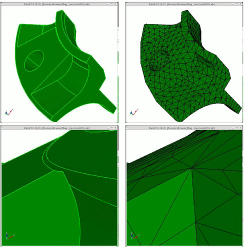
Figure 2. Demonstration
of the geometry tolerant meshing algorithm to remove a small groove.
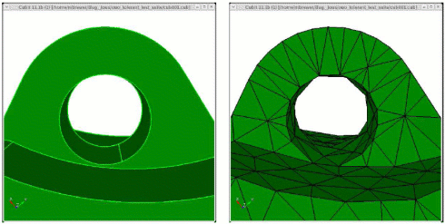
Figure 3. Removal of near-tangency
between two curves
In Figure 2, the algorithm correctly detects and resolves a near tangency
between two curves. However, the interior mesh edges inside the cylindrical
region retain much of their original shape. This causes a slight "bulge"
in the cylindrical surface. While this may not be desirable, it is the
expected behavior of the algorithm.
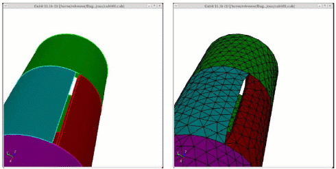
Figure 4. Tolerant meshing
performed on a simple assembly with pre-merged volumes
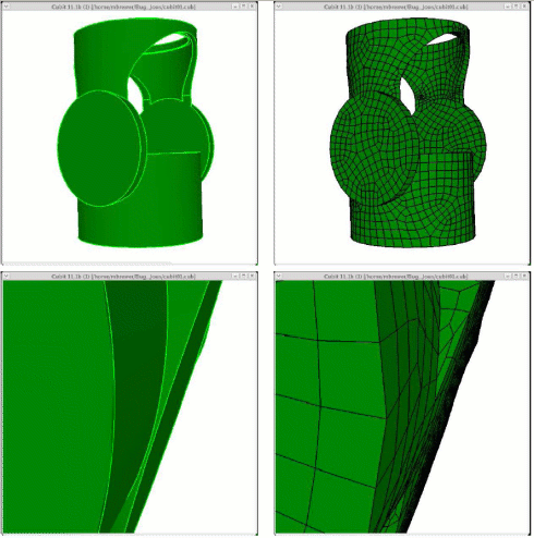
Figure 5. Quadrilateral
shell mesh generated using geometry tolerant meshing scheme. Note that
no hexahedral elements were generated.
Limitations
Accumulated geometric error
By performing the remeshing step on the original facets, we accumulated
discretization error. The original facets are an approximation to the
original surfaces, and the new facets are an approximation to the original
facets. Because of this, the final mesh may not respect the original geometry,
especially in areas of high curvature. However, in many cases this accumulation
does not seem prohibitive. Because the facets were created to respect
the original shape well, the initial discretization error is usually small.
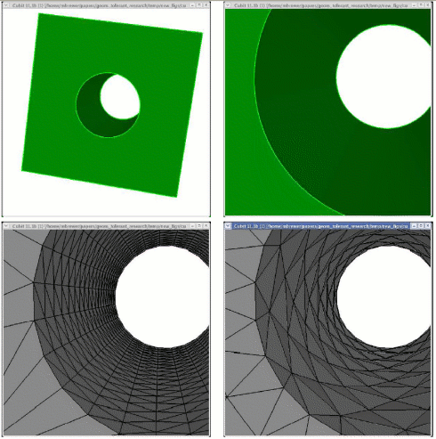
Figure 5. Accumulation of
discretization error in geometry tolerant mesh
Loss of Resolution due to initial faceting
If the initial faceting is coarser than the target mesh size, the refinement
step is required to make the edges closer to the target size. However,
for this step, we do no have a good way, yet, to maintain the geometry
well. More work will be required to determine it is feasible to do this
without accumulating additional error.
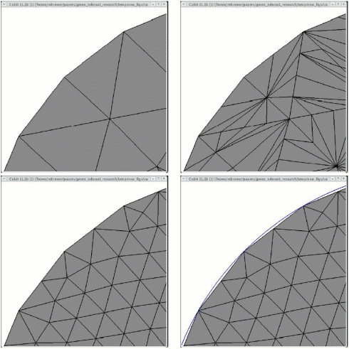
Figure 6. Poor resolution
of geometry due to coarse initial faceting
Surface to Surface proximity
The current approach only removes small features that can be detected
by the surface mesh. Since there are no elements filling the interior
of the volume, two surfaces that are close (but have no overlapping edges)
will not be flagged as small features. Regular geometry manipulation would
be required in this case to tweak or remove the surfaces. Figure 7 shows
an example of where the algorithm fails to recognize close surfaces as
distinct surfaces.
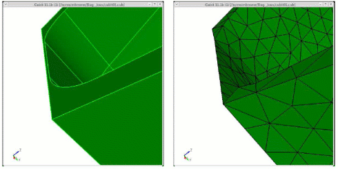
Figure 7. Demonstration
of geometry-tolerant meshing algorithm failing to recognize a thin region
that has no small edges or facets
Mesh size on fixed geometry entities
If a geometric entity is fixed, the original facet edges on that entity
are not collapsed regardless of how small, relative to the target mesh
size, they may be. Therefore, in the current approach, there is no mechanism
for coarsening the feature mesh edges in these regions.

![]() Cube-it 16.3 User Documentation
Cube-it 16.3 User Documentation![]() Cube-it 16.3 User Documentation
Cube-it 16.3 User Documentation


![]()